
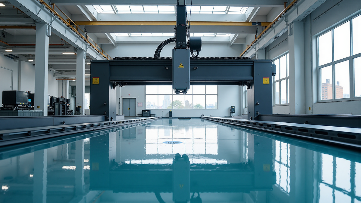
N-Series Gantry Machining Center (N-2518)
Rigid gantry machining center series N-2518 / N-3018 for large moulds and structural plates, gantry through width 1800–2000 mm.
- CategoryN-Series Gantry Machine
- Gantry 1800 mm, table 2500 × 1800 mm, 18.5 kWGMC-N2518
- Gantry 1800 mm, table 3000 × 1800 mm, 22 kWGMC-N3018
- Gantry 2000 mm, table 2500 × 2000 mm, 22 kWGMC-N2520
Price and lead time are quoted per configuration and quantity. Send us your part or capacity requirement and we will come back with a quotation.
The N-series gantry machining center is built around the N-2518 platform, a rigid double-column machine aimed at large moulds and heavy structural plates. It combines a wide gantry with a long X travel so that oversized parts can be face-milled, drilled and pocketed without repositioning.
Suitable Workpieces
The N-series is typically applied to large injection moulds and die-casting dies, thick die plates, automotive fixture bases and welded structural components. Its generous Y clearance also makes it practical to machine box-type and frame-type parts with tall features.
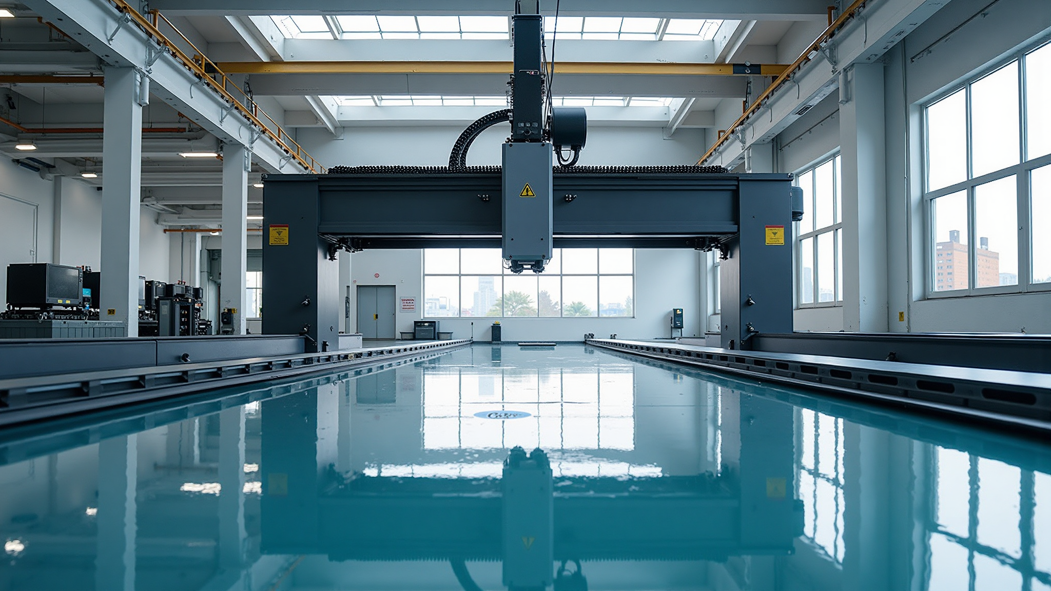
Typical Specifications
| Item | Typical reference range |
|---|---|
| Gantry through width | 1800 – 2000 mm |
| Worktable size | 2500 × 1800 – 3000 × 1800 mm |
| X / Y / Z travel | 2500 / 1800 / 800 – 3000 / 1800 / 1000 mm |
| Spindle speed | 30 – 5000 rpm (typical) |
| Spindle motor power | 18.5 – 22 kW |
| Tool magazine | 24 – 32 tools (typical) |
| Positioning accuracy | approx. ±0.012 mm / 300 mm (reference) |
| Table load capacity | 5000 – 9000 kg |
| Guideway type | box / linear roller, configuration-dependent |
These figures are typical industry reference values provided for selection; final configuration and quotation are subject to confirmed inquiry.
Structural Rigidity Highlights
A symmetrical double-column frame and a ribbed, stress-relieved base control deformation during heavy milling. The cross-rail and saddle are generously sized, and the guideway arrangement keeps the spindle axis stable even at extended Y positions.
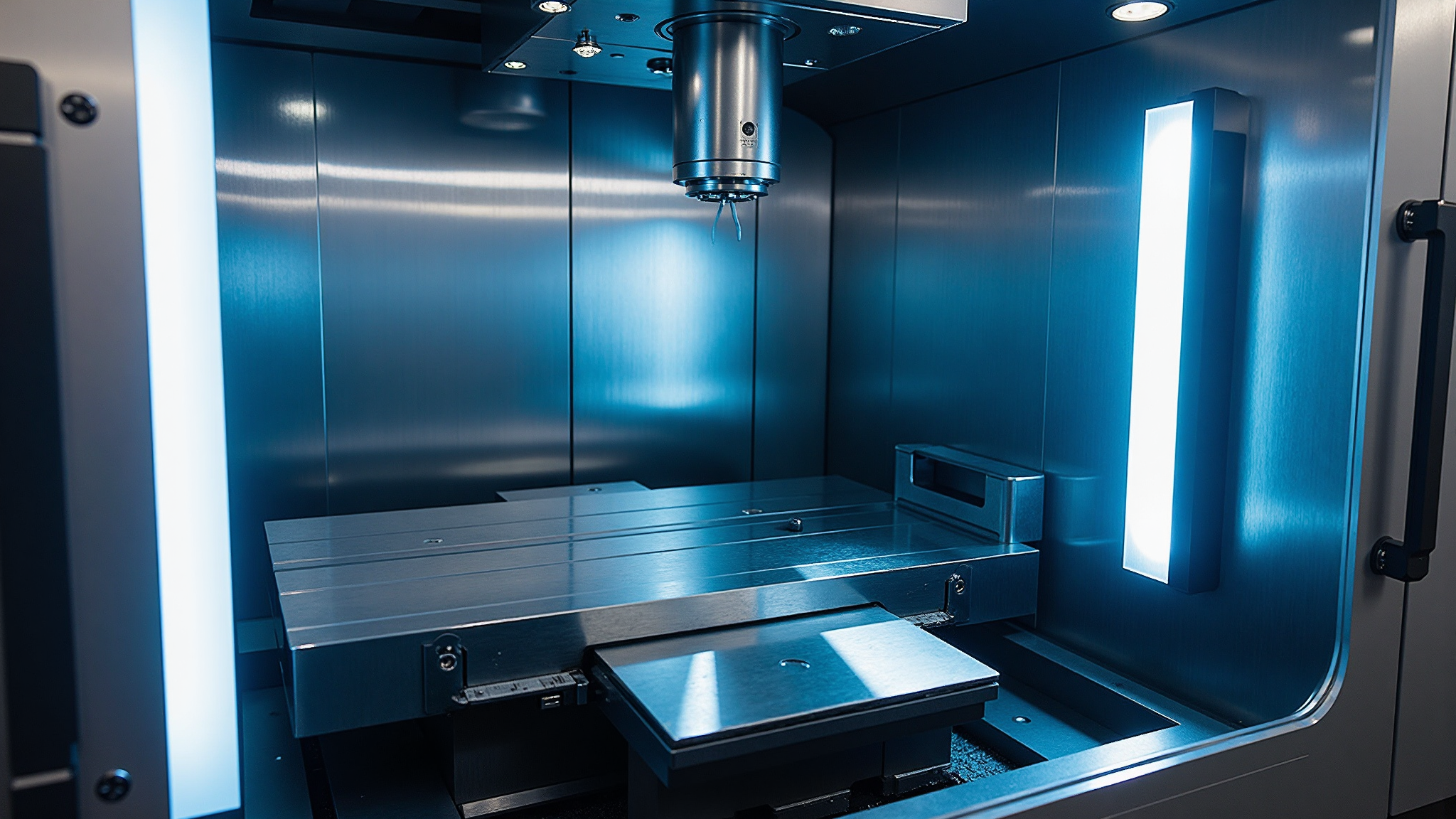
Selection & Foundation Installation Notes
Define the selection around the largest part footprint and the heaviest single workpiece, then verify spindle power and Z travel against the required cutting depth. A rigid, well-isolated foundation is recommended, and the machine geometry should be re-checked after anchoring and after a short run-in period.
Need a Different Configuration?
Tell us the parts you machine and the batch size — we will recommend a machine or process that fits.